|
Home
| 32KOmnibus
| 4sale
| 8L
| 8a
| 8e
| 8i
| 8s
| C
| FPGA8i
| blog
| cables
| cad
| computerlab
| decmateI
| decmateII
| decmateIII
| df32emul
| documents
| dsd410
| flipchip
| frontpanel
| kc8a
| la36
| lab
| omnibus
| papertape
| pc04
| repair
| rk05
| rl02
| rx02
| rx08
| sbc6120
| software
| tc01
| tools
| tty33
| tty38
| tty43
| ttycards
| tu10
| tu55
| tu56
| typeset
| vt78
|
IOB6120 Page
|
As mentioned on the SBC6120 page, Jim Kearney did an
expansion board for the SBC6120.
The original boards from Jim have a problem with the battery back-up circuit.
Basically, the batteries end up trying to run a TTL device, which runs the battery
down too quickly. In 2009, I decided to take the CAD drawings for Jim's board,
rework them a bit, and fix the battery back-up issue. I called my version 'iob9c'
because it ended up being my third version of it in 2009. Once I had done that, I
wanted to own one! So I got together with Robert Ribbeck and Jack Lowry to set up
a group buy in the Spare Time Gizmos
Yahoo discussion group.
In early January of 2010, I ordered 65 boards -- 48 for the group buy and another 17
for myself.
The way that board orders are priced, there's a $450 or so setup fee, then
a small charge per board. I anticipated that there might be later interest in a
smaller second run, so I took the money from the group buy for their 48, and
chipped in the extra money to buy some extras.
Long story short, that group buy fell apart, in a spectacular way, that
still hadn't really resolved itself. At least Jack and I had done our
parts. Dave McGuire now had those boards, and was still working
to assemble and deliver them.
That led to an odd situation -- the only "available" IOB boards were the
ones I had ordered for "round two". In early 2010, I had acquired components for
these boards, expecting the group buy to proceed, and eventually demand to appear
for "round two". That left me with a lot of money expended on IOB boards, and
without an obvious way to recoup. Finally, in 2011, I decided to give up on
"round one" and to assemble and sell "round two".
Note: Dave did assemble and deliver the original set of boards,
delivering the last of them around 2014 or so. He did this at considerable
personal expense, in time as well as money, and I appreciate his efforts!
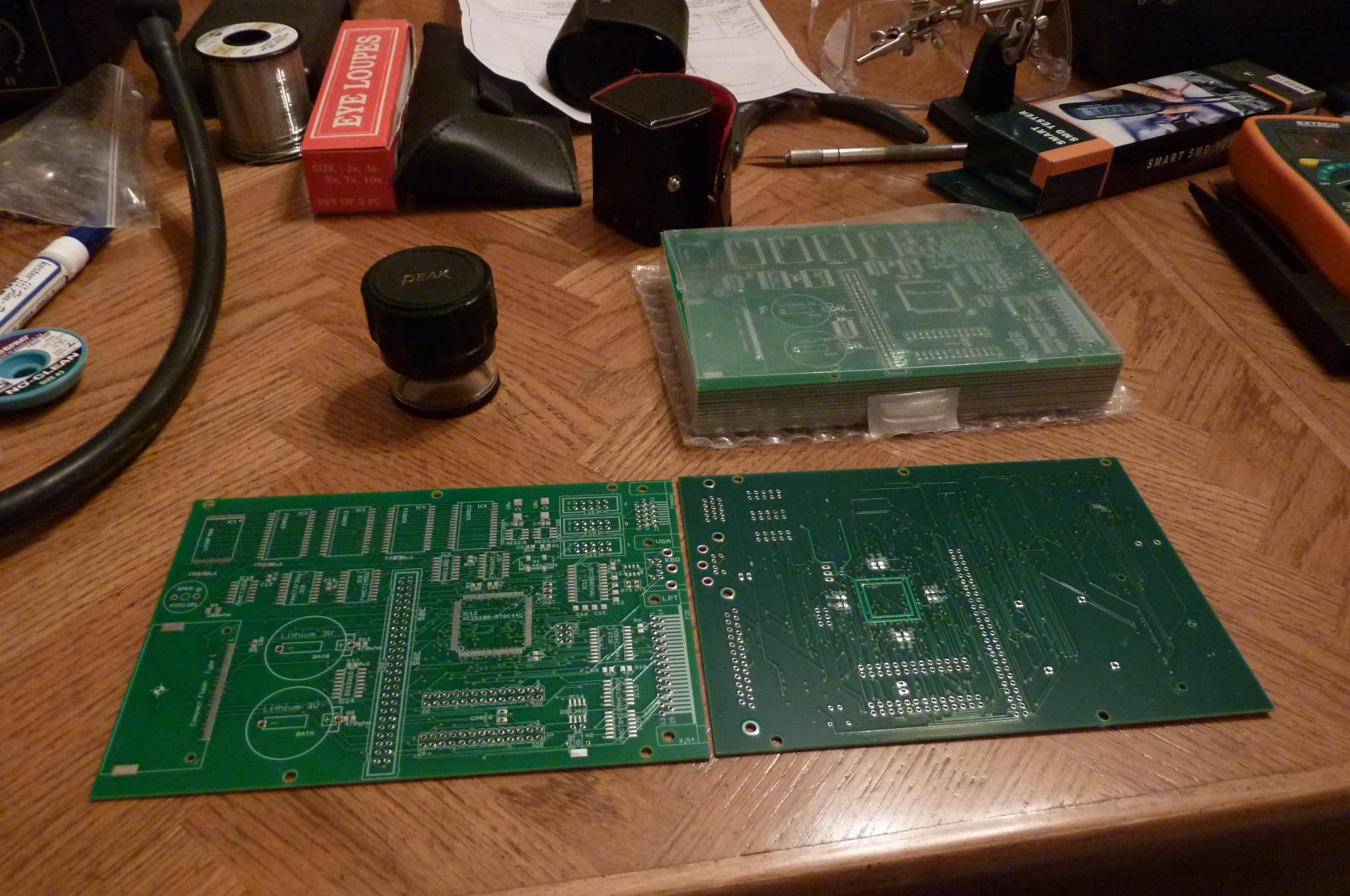
This was actually a big deal for me, as I had never done finely detailed
SMT solder work of the sort required to assemble these boards. The solder
connections for the flash chip, the FPGA, and the CF connector are about
0.5 mm apart!
I did manage to acquire the correct tooling, requisite skills, and courage to build one:
If you look closely at the pictured example, you can see that it has an Intel E28F800
flash chip installed in the upper left corner. The E28F400 flash chip is what the Jim originally
used in the IOB, but they are no longer manufactured or sold, and I was lucky to get a couple of
these, which are software compatible and mostly pin compatible (you have to connect an extra
address line with a solder bridge).
What I actually had for the other boards, however, were the newer 29F400 chips. These
are pin compatible, but they are not software compatible. That is, they will solder to the
board without board modifications or jumpers, but the programming sequences used to load their
initial contents are rather different, and not nearly as compatible as I'd originally thought.
The flash contains the FPGA programming as well as extensions to the SBC6120 firmware,
and initial programming of the flash is done with a SBC6120 firmware command, and a long slow
download:
Since this command was actually what I was debugging, It took quite a bit of time to
get that working, so that the flash command could tell automatically which flash chip was
installed, then modify itself to correctly program the part.
Long after learning to hate the 29F parts, I got that done and sent the firmware modifications
back to Bob Armstrong.
I had recently updated my Windows desktop to Windows 7 64-bit, and the old Willem
programmer I'd used before didn't work with Windows 64-bit. While watching bytes load into
these boards over and over (until my code worked), I ordered a replacement for my Willem
programmer, an all USB version, which was compatible with 64-bit Windows. I also ordered
the correct adapter for the flash chip along with it. In no time at all, I was able to
program the rest of my 29F400 flash chips, and then was ready to assemble the rest of the
IOB boards, test them, and rework them until they got the green sticker:
These boards have been mostly sold. The original asking price for the group buy
was $215, which included shipping. I got my bare boards a little cheaper, but then again
had to buy all the tooling and actually build the things up, so I sold mine for the same
price.
As of 12/2011, I have a total of 4 IOB boards.
One has the E28F800, one has a flash chip socket with a 29F400 in it, and two have the
29F400 soldered down, like the others pictured. (Since I have two SBC6120/FP6120,
my plan is to retain at the very least the two oddballs for my own use.)
Note that so far, we've built some nice hardware and played with some firmware,
but we haven't made it do much yet.
Last updated on 07/12/26 07:49 | |||||||||||||||||||||||||||||||||||||||||||||||||||||||||||||||||||||||||||||||