|
Home
| 32KOmnibus
| 4sale
| 8L
| 8a
| 8e
| 8i
| 8s
| C
| FPGA8i
| blog
| cables
| cad
| computerlab
| decmateI
| decmateII
| decmateIII
| df32emul
| documents
| dsd410
| flipchip
| frontpanel
| kc8a
| la36
| lab
| omnibus
| papertape
| pc04
| repair
| rk05
| rl02
| rx02
| rx08
| sbc6120
| software
| tc01
| tools
| tty33
| tty38
| tty43
| ttycards
| tu10
| tu55
| tu56
| typeset
| vt78
|
RasPi 0W Tester
This page describes the changes made to Warren's tester to interface it to the Raspberry Pi 0W. (I chose the 0W for it's low cost, fast access to the GPIO pins, and built in wireless.)
This discussion assumes you've assembled the DOS tester as a starting point (with the exception that there is no point in assembling the LPT: port header and cable, nor installing the power connector).
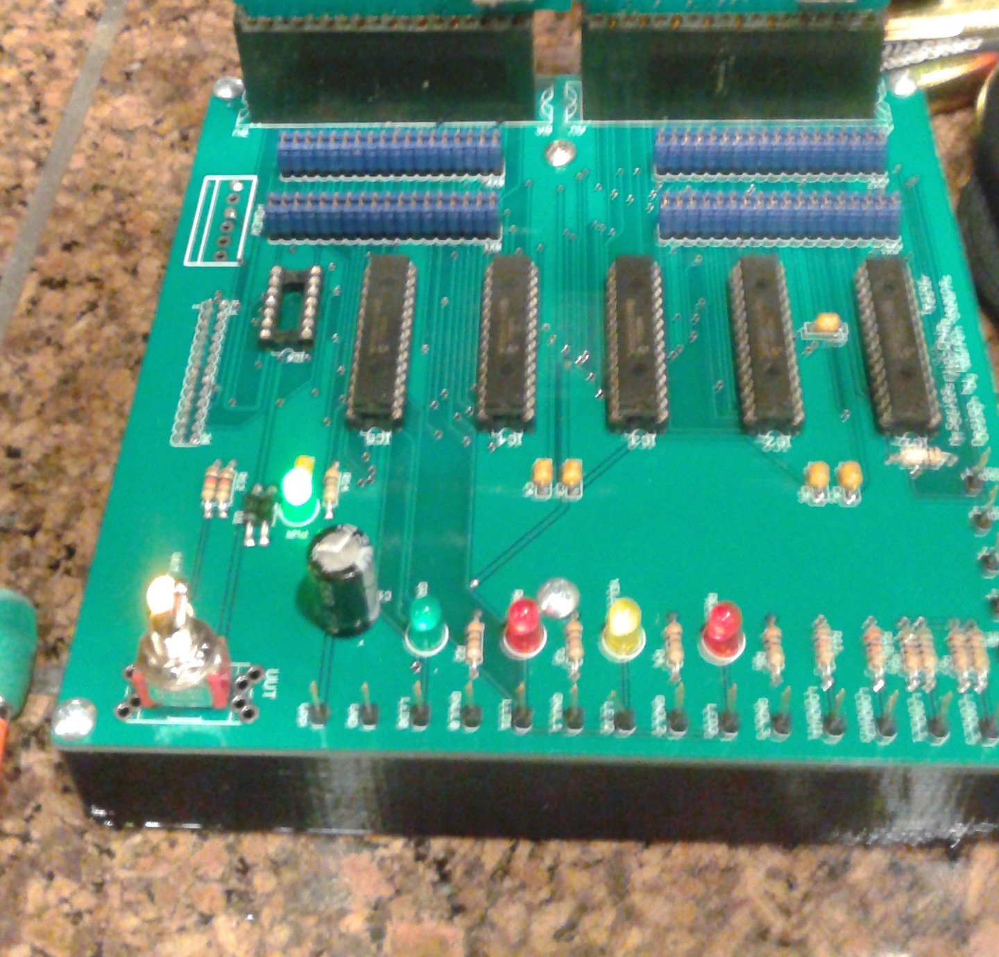
Assembled Pi Tester |
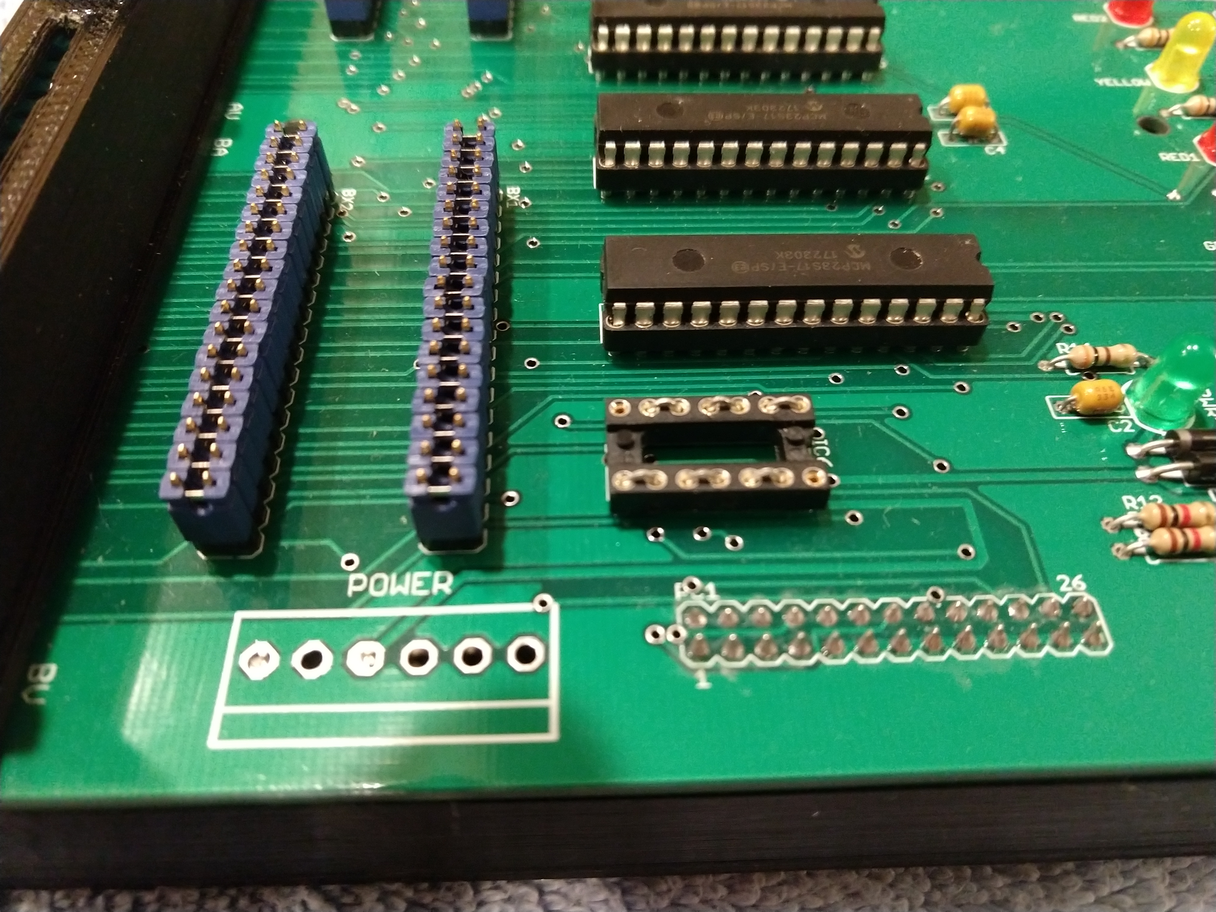
IC6 Jumpering |
I have prepared this document to help document the changes described here.
First thing, remove IC6 and install jumpers in it's place, as shown above.
Acquire some shrouds, a cable, the resistors and capacitor, 2x13 and 2x26 right angle headers, and a Raspi 0W basic starter with power supply and cables. (I used adafruit.com, as they seem to cater nicely to this sort of thing.) You want to buy a Pi without a pre-installed header, if you intend to fit the result in the box!
First, remove all the 1x1 shrouds from the cable. This is tedious, but nearly as bad as trying to make the result with wires and a crimper! You will need to deflect the plastic tab that holds the pin socket in, then pull out the pin socket.
Next, install the pin sockets as described in the above document. You'll need to insert each pin in the correct location and with the correct orientation in the shroud until the plastic tab clicks to lock it in place.
The result should resemble the one pictured here:
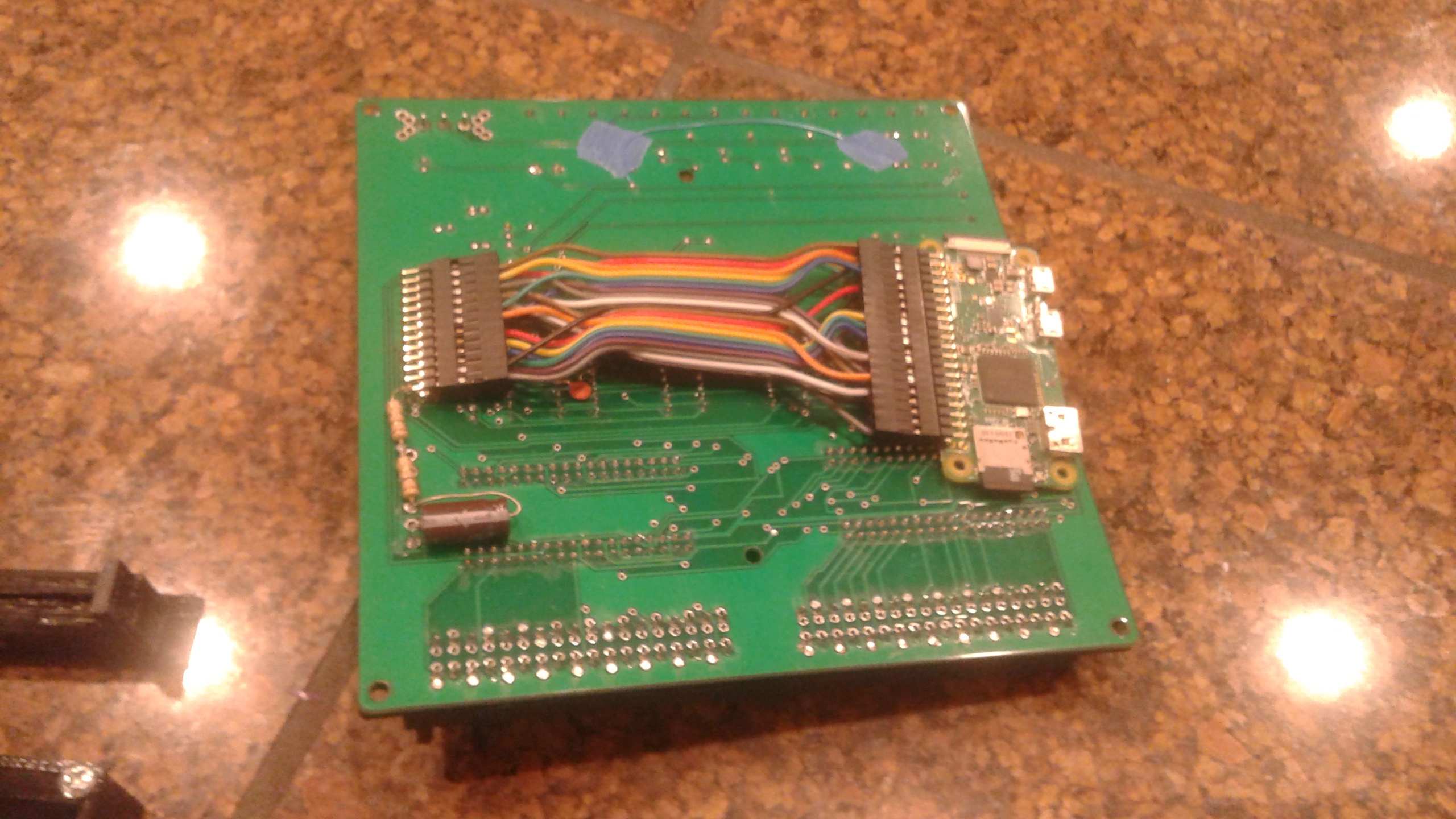
Pi Adapter Cable |
Install the 2x20 right angle header in the Pi 0W, with the pins facing off the board. (This is why you wanted a Pi without a pre-installed header.)
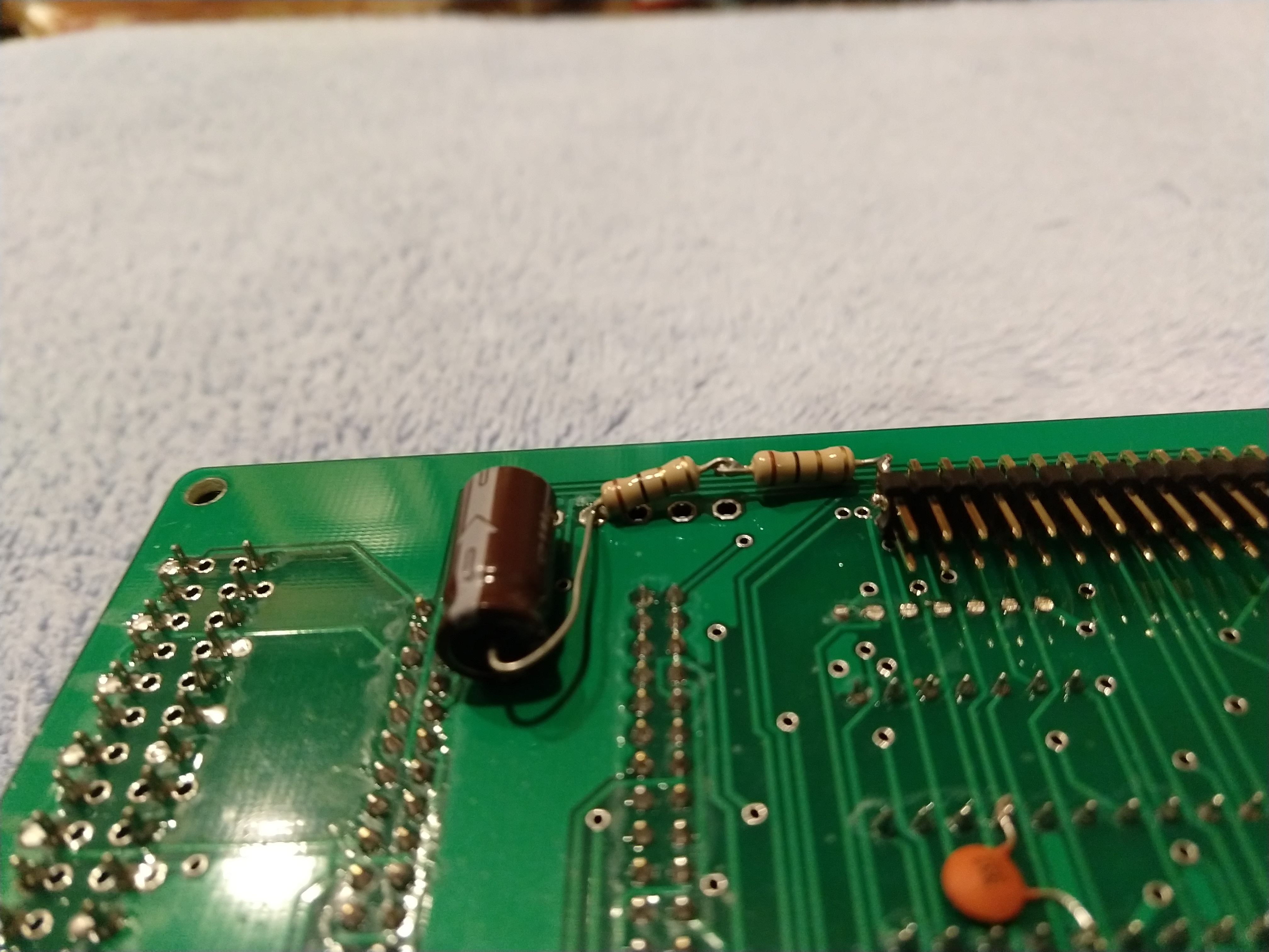
Trimmed IC6 pins |
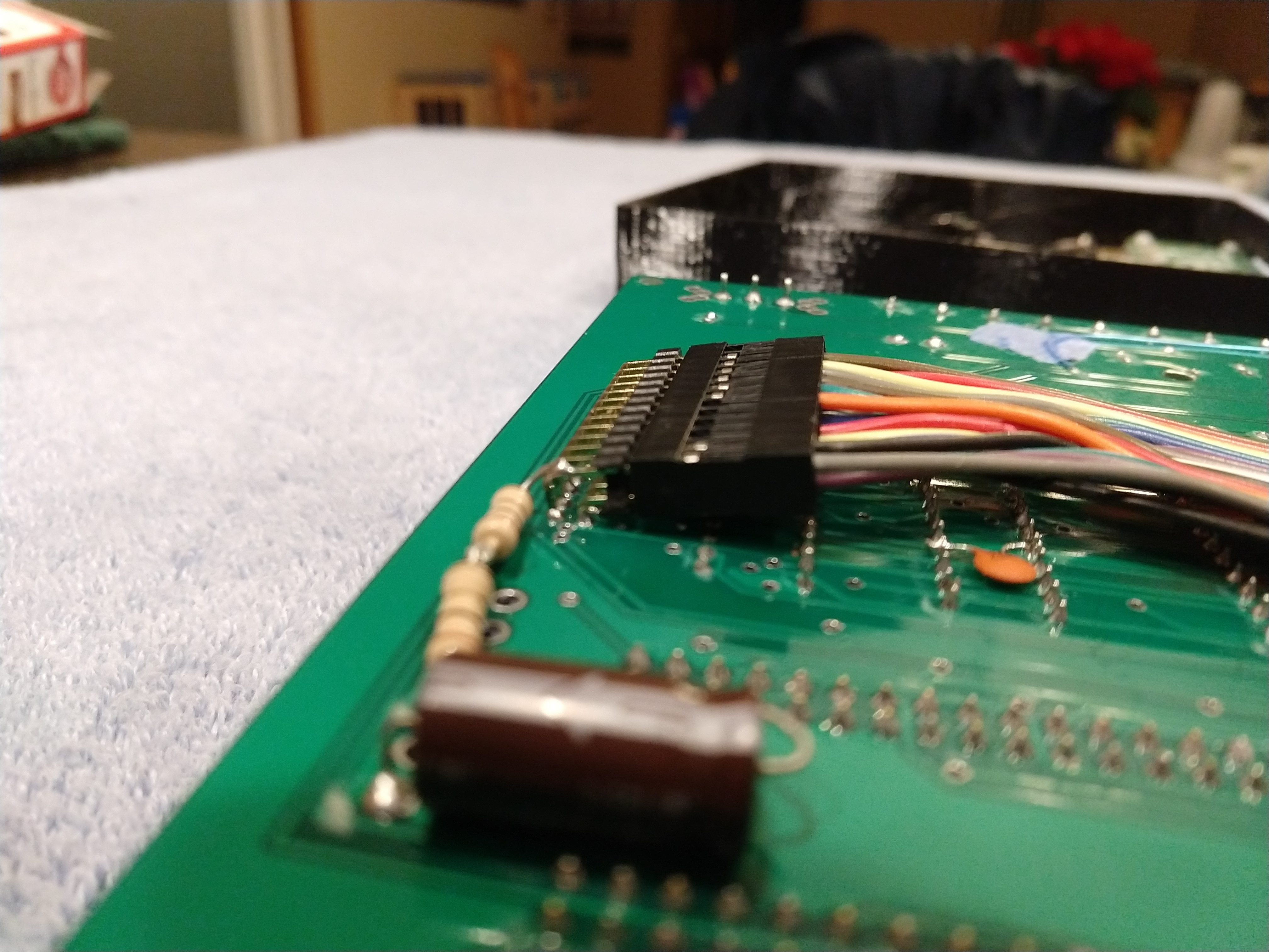
Tester Cable Connection |
Click on the "Trimmed IC6 Pins" photo above, and flush-trim the pins of the side of the IC6 socket nearest the header position, as shown.
Fit the cable's 2x13 shroud over the 2x13 right angle header, then install the header in the tester, facing downward and inward. The result should be angled slightly, as shown in the close-up at the right above. This is why you didn't want to bother installing the header when you assembled the tester board!

Inrush Limiter |

Inrush Limiter |
Next, install the resistors and capacitor needed to run the tester safely off of the RasPi's supply brick. (These form an inrush limiter, keeping the flip chip from sucking down all the available +5V when you turn it on.) The components attach to the tester PCB using their leads, which can be trimmed after installation.
You'll need to install a bootable SD card in the Pi 0W. I have images for that, but they are quite large. Let me know if you need them, or you can craft your own.
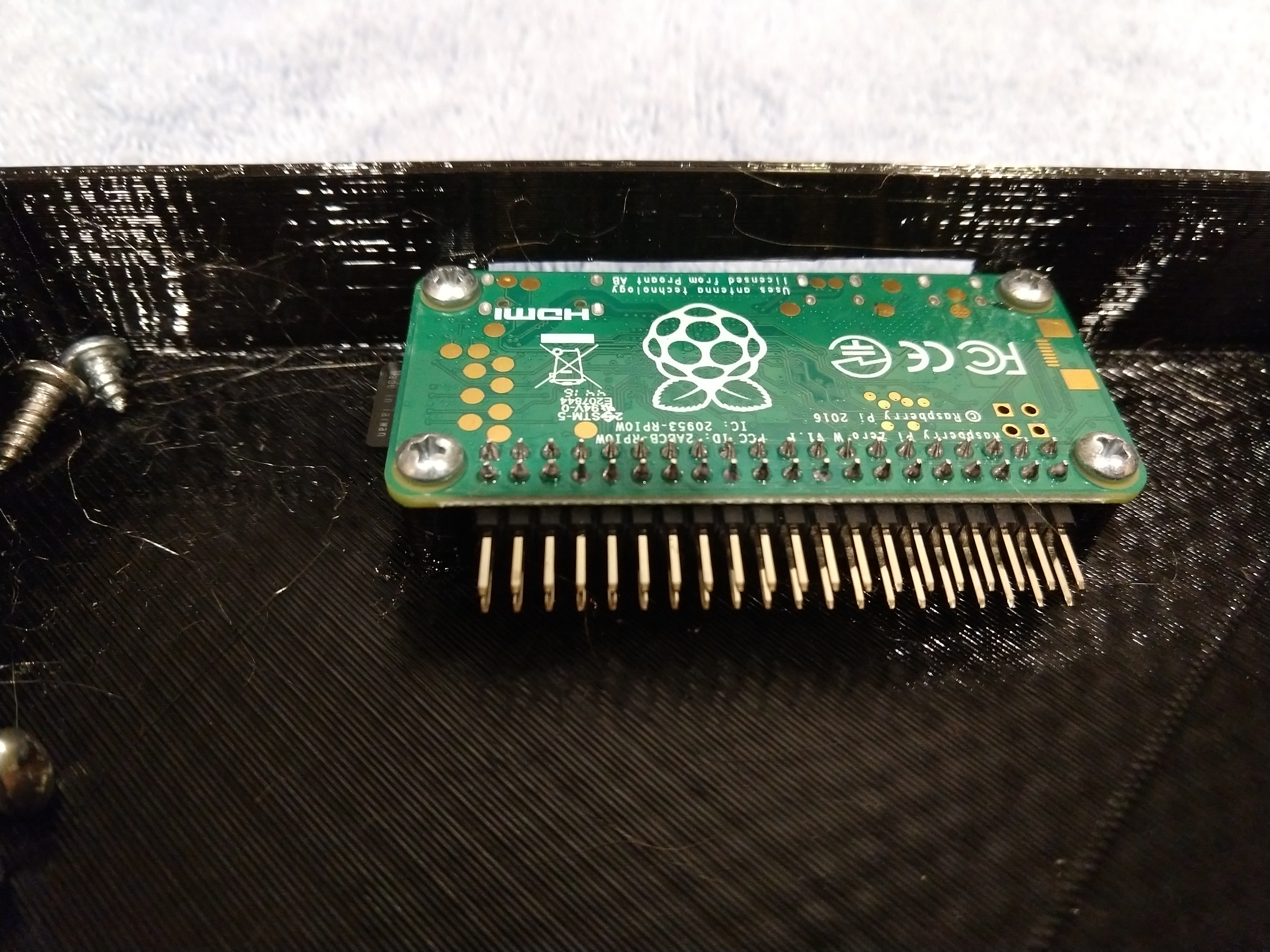
Pi 0W in the box |
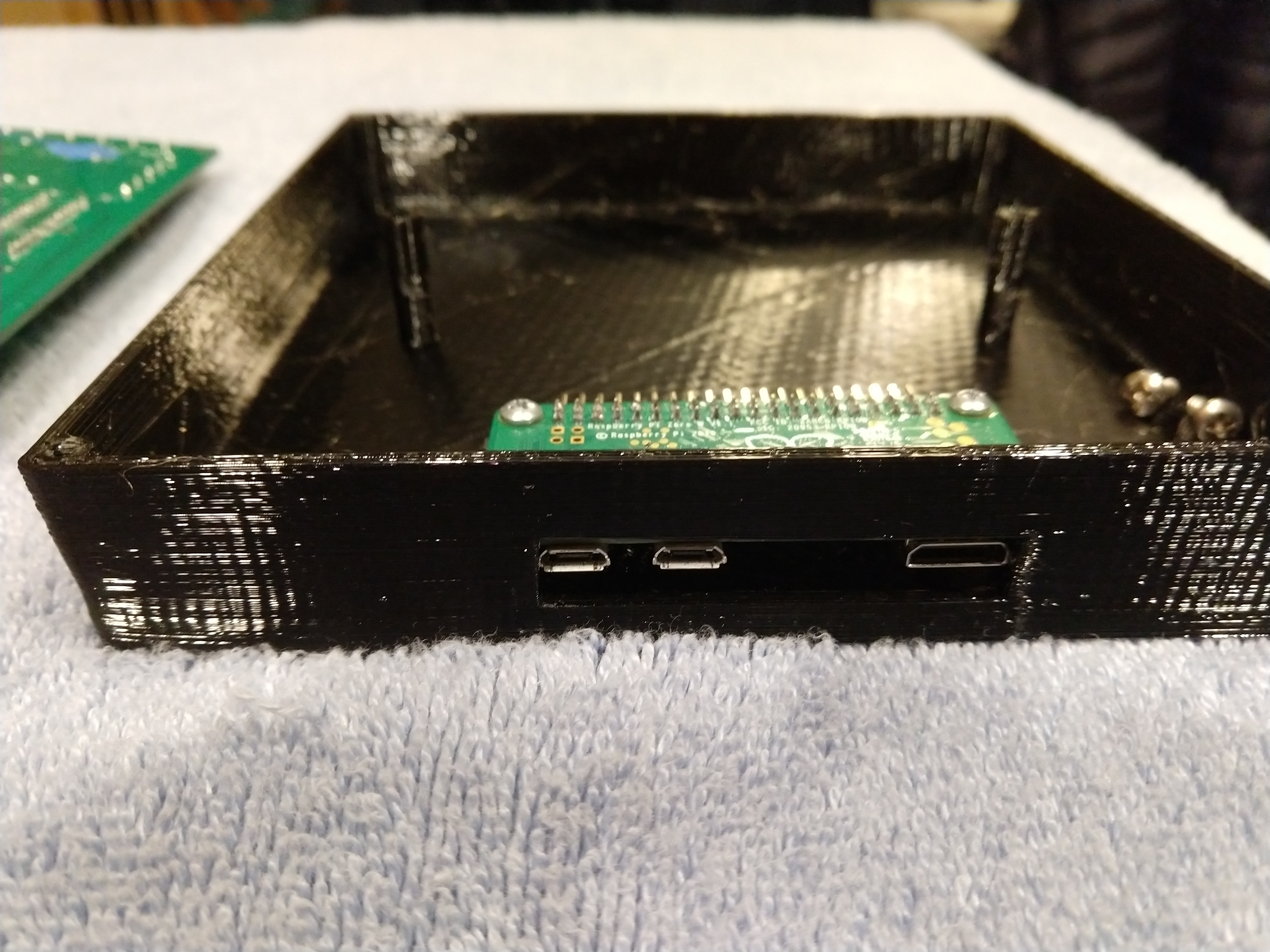
Pi 0W in the box |
Install the Pi 0W into the box using #4 3/8" self tapping screws or equivalent. Be sure the ports face out the slot in the side of the box! Attach the cable you made to the Pi. Double check that pin 1 lines up with where it should, on the Pi side and also on the tester side.
There will be limited range of movement of the tester PCB, but you should be able to attach it to the box using #6 3/8" self tapping screws or the equivalent.
If you are using your own fresh install image for the Pi, use the cables which came with your starter kit to install the software, set up SSH access, etc. You will also probably want to use apt-get or equivalent to install "subversion", and set up user "tester" as having access to GPIO and network setup groups. The file Pi-Setup.txt has tips for this.
Even if you are using my images, you will likely need to set up the wireless SSID and password using the starter kit's cables.
Using the cables as above or using SSH, log in as "tester" (or "pi", if you couldn't be bothered). My images use password "tester123". Anyway, issue one of these commands:
- svn co http://svn.so-much-stuff.com/svn/trunk/pdp8/warren/RasPi/
-
- svn update .
Now do "cd src", "make", and "./tester" to get the tester software running. The tests themselves live in ~/TESTS.
|
Last updated on 02/25/23 02:21 |
||||||||||||||||